Wednesday, December 31, 2008

The Whole Enchilada

To commemorate the end of the year - and the end of major construction on the ElectroJeep - I made a Google Sketchup model of all the components. It still needs some tweaking - but here is a picture of the work-in-progress. You can download the actual model in the Documents link section to the right (beware - it is large - 23MB).


Happy New Year, and may all your vehicles be electric.

Charger Inlet

I changed my mind - I wanted to get the charger going so that I could keep the battery pack easily filled up. I started with a plastic cover plate, and drilled a hole in it to match a marine outlet that I had purchased earlier:


The cord for the charger comes out in an outlet box in the former gas tank filler opening:


I threaded the cord through the plate, and attached the wires:


Finally, I completed it by attaching the plate to the box:


Here it is, plugged in and charging:


To avoid damage to the batteries, I am only charging to 330V for the pack (this is roughly 12.7V per battery). I will charge the individual batteries to equalize. This will only be necessary until my battery management system shows up (I already have a PakTrakr installed for monitoring purposes).

Back Home...

Nothing really to report, but I adjusted the layout of the site and added a bunch of links to the right. Most significant are the document links - these are PDF plans of all the components that I designed for this project.

Today - I'll see if I can get the potbox mounted.

Tuesday, December 23, 2008

It's (almost) Alive!

Monday morning - I hooked up the last three wires:

  • Keyed +12V to relay box
  • 12V ground to relay box
  • DMOC to 12V ground
I then turned the key, heard the contactor "click" and then - nothing.

I've been here before, of course, so I knew what to do. I hooked up a computer and fired up Azure Dynamic's diagnostic ccShell program. It was registering error code 16 - which I was familiar with from Tim's experience. I checked the grounds, and then set the variable EE2DisableChargedError to 1 which makes the controller ignore the error code 16.

One more time, turning the key on and - noise! Ugly grinding noise, though. The same whether in neutral or in gear, so I'm pretty sure it is coming from the motor itself. I've been here before, too - so I contacted Azure Dynamics tech support. We've had a couple of interactions, with them requesting data dumps & experiments, and me returning data to them.

No results yet - it can move (slowly) forward and backward, but not enough to back it down the driveway. When I get back from vacation, I hope to be able to finish this in the next week or two...

Pushing toward Final Assembly

I'll be away from the Jeep over the Christmas holiday, so I wanted to get as much done before I left as I could. So, I stayed up until 2:00AM Monday morning working on things. I did some potbox hackery to attach a threaded rod that will (eventually) be attached to the gas pedal. Basically, just a 10-24 machine screw with nylock nuts holding it to the potbox arm, and holding an angle bracket on (the nylock nuts are not tight on the angle bracket - it needs to be able to rotate). The threaded rod goes on the angle bracket, and will be pulled by the accelerator pedal as you depress the pedal:


I attached all the interconnects, flexi-cables, and PakTrakr connections to the lower rear box:


Between the lower rear box and the upper rear box, there are a CamLok connector and a 400A fuse. In keeping with my "no exposed 312V connections" rule, I put the fuse in an electrical conduit box. The red cable is very stiff, so I made the other side a "FlexiCable" connection to give me more wiggling options:


The red end of this cable attaches to the upper rear battery pack. It goes through an opening in the metal, so I added armor to protect it. I cut a chunk of leftover conduit to fit:


And then heat-shrink-wrapped it in place:


And there it is, attached. The interconnects and PakTrakr connections are also finished in the upper rear rack:


I then hooked up temporary interconnects between the upper rear rack and the under-seat racks, and between the batteries. Because I underestimated the amount of 4/0 cable, I had to order some more. It's not here yet, so I grabbed some 2-gauge battery cable and made up some two-wide cables as temporary interconnects (using 2/0 lugs). The circular area of two 2-gauge cables is about the same as 2/0 gauge cable - enough for my purposes for now (it will get replaced with 4/0 cable before I do any significant driving):


And then I finished the hookups in the engine compartment. It was getting late at this point, so I took some shortcuts - I have not heat-shrink-wrapped the interconnects, and I need to adjust the shortest ones so the batteries will line up properly. Also visible in this picture are the relay box, tie-wrapped in its final location in the upper left corner of the picture:


And here is the top on. Unfortunately, that front interconnect is still too tall, and the top does not fit all the way down. I will deal with that after vacation. For now, I'll live with a hood that does not quite close all the way (it latches but does not fully close):


And then it was time for bed.

Feeding the Snake

In their book, "Convert It", Mike Brown and Shari Prange say the process of feeding heavy cable through conduit is like feeding an uncooperative python. After having done it myself, I think it is more like feeding a live python to a live anaconda... but I managed to get it done.

First, I had to remove the conduit from the Jeep. If the conduit is not fairly straight, the cable will hang up on the twists and turns and not feed through. So, I took it down to my laundry room where it is nice and warm, and proceeded with the feeding.

The long cable has both the 4/0 cable as well as a 10-gauge cable (for the most negative attachment to the charger). So, I taped them together at roughly 12-inch intervals. I then fed a plumber's friend through the conduit, and taped the cables to the wire:


With liberal applications of electrician's slime, and alternating pushes and pulls, I managed to get the cable through the conduit:


The shorter cable (from the rear seat racks to the front rack) went more easily - it is just the cable, and a shorter run, so I was able to push it right through (again, with a liberal application of slime). I finished the ends (one end a CamLok connector, the other end a standard lug):


I also finished the ends of the longer cable - lugs on both ends:


And then I replaced the conduit on the Jeep, but now, with cables!

Brakes, U-Joints, Transmission

I also finished the brakes and transmission. Because of the under-seat racks, I needed longer emergency brake cables. To change them, you pretty much have to dismantle the whole rear brake assembly. So, I put new shoes and drums on while I was at it. Here is the old assembly:


And here are new shoes, springs, etc. (on the other side):


And here is the new drum. The old drum is pretty much rust-colored:


Here are the new emergency brakes hooked up to the handle. I got two Jeep Wrangler YJ '91 or later passenger's side cables, part number 52007522, and hooked them up. I had to extend the threaded rod to meet the cables. This is all as documented on this link at 4x4 Wire. A functional emergency brake is a necessity for an electric vehicle, since there is no "compression" to act as a "motor brake":


I also installed new heavy-duty U-joints on both sides of the drive shaft, and new straps and bolts on the differential end:


Not shown, but I filled the transfer case and transmission with fluid. I used a suction device to fill the transfer case, and I filled the tranny from the shifter rod opening until it started to drip from the fill hole.

Shortening the Motor Cable

The main motor cable was far too long - I would have had to wrap it around the engine compartment 2 or 3 times - so I asked Azure Dynamics about it, and they had instructions on shortening it. It is pretty straightforward. First, you remove the shrink wrap and/or electrical tape from the end of the cable:


Then you strip off the heat shrink as far down as you need it (make the cable longer than you expect - much easier to cut it shorter later if you need, hard to stretch it longer...):


Trim the grounding braid, again, a little longer than you expect:


And then, label the individual wires below the point where you will cut them. Cut the "C" cable 1.5 inches longer than the "B" cable, which is 1.5 inches longer than the "A" cable. Crimp on 2-gauge lugs, and you're nearly done:


The last step, not shown, is to heat shrink over any extra grounding braid, and tape up the 3-phase cables as you found them originally. With this mod, I have a little slack from the motor to the controller, but not so much that it will be dragging on the ground. I removed about 4 feet of cable.

More 12V hackery

I've actually been so busy on the Jeep the last couple of weeks, I've not had time for blogging. The next few posts will make up for that...

First, I did some work on the 12V relay box. I made the cables that will attach the box to the DMOC controller and to the dash instrumentation. The DMOC cables use GM WeatherPack connectors - which are very handy things, well-sealed and robust.

You start by collecting your pin, seal, and crimper:


Push the wire through the seal, and crimp the pin on to the wire and on to the seal:


Push the seals through the connector, close the end, and you're all done. About 1 minute per pin once you get the feel of it. Here is the relay box with its cables attached (the ones at the lower left connect to the DMOC, the ones at the upper right connect to the dash instrumentation).


After looking closely at the wiring diagram, and after deciding to get a 120/240VAC to 12VDC power supply to integrate into the system, I realized two things. First, the glass fuses were pretty much all for the AC power supply and relay. Second, with those fuses gone, there was plenty of room in that box for the heater contactor. So, here is, I believe, the final 12V diagram:


And here is the assembled box, integrated in (the dash wiring is not complete, nor is the heater wiring, but the box is hooked up to the keyed 12V (yellow wire on the left), ground (black wire), and the DMOC:


The current wiring diagram PDF is, as always, here.

Tuesday, December 16, 2008

Odds and Ends

I also test-fit my copper interconnects, and found I had made some of them 1/8" too tall (and a few of them are marginal in their length). Fortunately, changing the 90-degree bends to 75-degree or so bends dropped the height just enough and increased the length just enough:


Also, this Saturday I got started on getting the transmission put back together for real - I hooked up the wires, reattached the tail cone (including a gasket), and read up on replacing the U-joints. That's as far as I got, though, since winter has arrived with sub-zero temperatures, so I'm working on "things that can be accomplished inside" for the moment.

Monday, December 15, 2008

Controller Power Input Cables

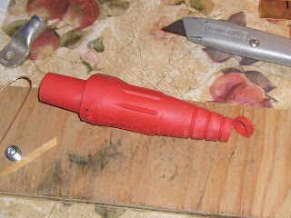
Remember the Cam-Lok cable connectors? I finally installed a couple of them. I built the cables that are the final terminal into the DMOC controller. As you may recall, 4/0 cable is too thick to pass through the strain relief fittings on the controller. After debating several options, I decided to use 3/0 cable for this section. I got a few feet of red and a few feet of black and went to town.

First, I cut the end of the Cam-Lok connector so it snugly fit over the 3/0 cable:


Next, I slimed the cable with electrician's cable-pulling slime:


Then I pulled the cable through the housing:


I stripped the end the required length (somewhat longer than a crimped lug requires):


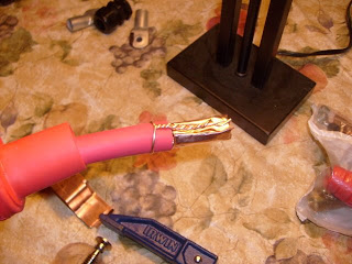
Then I wrapped the copper shim around the end, and tightly wrapped the copper strain relief wire about 1/2" below the stripped end, twisting it and laying it against the shim:


I then installed the brass connector and torqued the screws down to spec:


A touch more slime, and I pulled the shroud over the connector and inserted the retaining screw. All done!


I did the black cable too:


There is a problem, though. 3/0 gauge lugs will *not* pass through the strain relief bushings. And they need to - the tolerance on the DMOC is too tight, the ends of the lugs need to be inside the bushings. Also, 3/0 lugs are too wide - I would need to cut the end of one down (as shown in sharpie on the lug to the left). 2/0 lugs, as shown on the right, are "just right".


So, I clipped a few of the fine wires out so the remaining wires would fit snugly in a 2/0 lug, and crimped it and heat-shrunk it (after making sure the bushings were already on the cable *above* the lug connection - oriented properly). A little application of slime let me slide the bushings over the whole thing:


And here are the completed cables test-fit (but not bolted on yet):


Despite the fact that the overall system uses 4/0 cables and lugs for everything, I think this short 18" stretch of 3/0 cable funneled into a 2/0 lug won't affect performance too severely - it is a short distance, and the resistance delta between 3/0 cable and a 2/0 lug at this distance is nearly too small to measure. In fact, I took my multimeter to identical lengths of 4/0 and 3/0 cable, and I could not find any difference in the measured resistance.

Making FlexiCable

There are a couple of problematic connections in my battery layout. Particularly, the connection between A4 and A5 in this diagram is tricky. I tried making a traditional cable, but the 4/0 cable I'm using does not flex enough. So, I improvised. Looking up the specs on welding cable, I found that three 2 gauge cables are nearly identical to one 4/0 gauge cable, both in circular area as well as specified ampacity. So, I cut and stripped three lengths of 2-gauge cable (here shown next to 4/0 gauge lugs):


I firmly taped the three together, then fit 4/0 lugs onto them...


...then crimped the snot out of them (after all, who wants snotty cables?):


Here is the crimped flexi-cable:


And here is me flexing it one-handed. I could not come close to flexing the 4/0 gauge cable like this:


I double-heat-shrink-wrapped the ends:


And here it is, snug in its location: