Monday, September 2, 2013

BMS Wiring, Part 1

Today, I did some wiring toward getting the BMS in place.

First, I added some wires in the passenger's side of the rear compartment.  The green extension cord plug will eventually be the 120VAC battery warming power supply.  The green cord going into the cable gland and the silver thermocouple wire are also for the battery warming system (for the front box).  The white extension cord is for the BMS loop:


Here is the inlet for the battery warming plug.  I'm not going to do much more on this part for now (it's still pretty warm :-) but I wanted to get the hole-drilling and cable pulling out of the way:


The green, white, and silver cables go through the floor of the rear compartment to this LiquiTight conduit gland:


 The conduit proceeds forward along the wheel well...


...under the passenger-side rocker...


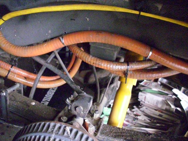
...and ends up in the engine compartment.  The silver thermocouple will go into the battery box; the white as mentioned will carry the BMS loop to these cells.


With the cabling out of the way, I wired up the BMS controller.  I went back and forth on whether to put this under the dash or in the rear - in either case, we needed some signals routed between front and back.  The deciding factor was that this placement is much more convenient to work on:


Here is everything all closed up and connected.  I tried plugging an EVSE in to see whether the kWh meter lit (and the charger light lit) but, no joy in Mudville tonight - the EVSE flashed a "line cord fault" indication.  I suspect I have the pilot and control lines reversed.  But for now, this *looks* pretty:


Here is the wiring diagram for the BMS.  I have not yet done the inter-cell connections (shown here in magenta, but I'll use white wires).  The PDF of this diagram can be found at this link.

So, this is probably as far as I get for the next few weeks - but I look forward to finishing the BMS wiring and trying a quick top-off charge cycle...

EDIT Sep 3 2013:  Swapping the PRX and PIL lines on the J1772 AVC1 unit fixed the problem!  I verified that all the other circuity is installed properly and working - connecting the cell loop (with no cells) causes the charge relay to engage, the 12V power supply is working, and everything seems happy.  The circuit diagram for that circuitry has been updated, as has been the previous post.

Sunday, September 1, 2013

Charger Control Electronics

"Well, we've tried every device and you still won't talk - every device, that is, except for this little baby we simply call 'Mr. Thingy.'":


OK, perhaps a little more explanation than this obscure Far Side reference is in order.  As mentioned before, with top-balanced lithium cells, you need to shut off charging current if any cell hits the high-voltage cutoff point (3.6V in my case).  Some chargers have ways to do this with a signal from the BMS.  But every charger is different.  I may want to change chargers some day, and in fact may want to experiment with an off-board charger for fast charging, so I created Mr. Thingy.  All Mr. Thingy does is provide a place to mount:

  1. A 40-amp solid state AC relay which can turn off the charger in a high-voltage-cutoff event
  2. The circuit board which handles the J1772 pilot and control signals
  3. The 12 volt power supply which powers both the relay coil as well as the "I'm plugged in, don't drive away you dummy!" light and interlock
  4. A kilowatt-hour meter to keep track of electricity used during charging
  5. Various plugs and receptacles to make switching between J1772 and a regular extension cord, and between the on-board charger and an off-board charger, convenient
All of this in an 8x8x4 inch box!  Here is the circuit diagram:


You can find the PDF of this circuit diagram here.  And here is the completed enclosure, mounted and attached:

For those who do not want to open the PDF, here is the note from that PDF explaining operation:

If the inlet 10-30P plug “B” is unplugged from the J1772, then the AVC1 will not have ground and will therefore not handshake with the J1772 EVSE, preventing any power from being present on the 10-30R receptacle labelled “A”. This is intentional.

When unplugged from the J1772, the 10-30P plug labelled “B” may be plugged in to a NEMA 10-30R receptacle for direct charging. The on-board charger can be unplugged from the 10-30R receptacle labelled “C” and another charger plugged into it for higher-power BMS-controlled charging.

J1772 Inlet from Tucson EV has the 2.74k ohm resistor preinstalled between PRX and ground.

All high-current 240VAC power wiring is 10 AWG.

EDIT Sep 3 2013:  Per this post, this did not quite work initially - the EVSE indicated a "line fault" .  Swapping the PRX and PIL lines on the J1772 AVC1 unit fixed the problem!  I verified that all the other circuity is installed properly and working - connecting the cell loop (with no cells) causes the charge relay to engage, the 12V power supply is working, and everything seems happy.  The circuit diagram for this circuitry has been updated, and now matches this updated PNG:


Strapping the Cells

In the earlier days of DIY lithium conversions, conventional wisdom was that batteries needed to be tightly strapped - even so far as using threaded rod and metal plates to compress them together.  It was believed that this prevented bulging - kind of like keeping the smoke from escaping.  It turns out that bulging is entirely avoidable - just don't abuse your cells with over-charging or over-discharging.  However, it is convenient mechanically to group the cells together.  It makes it easier to load them in the racks, too.  So I got some poly strapping equipment and banded most of the cells in groups of 3, 4, or 5.

Use is pretty straightforward.  Place a length of strap around the thing you want to bind, and put a metal clip in place, then thread the strap through the ratcheting strapping machine:


Tension the strap as desired (being careful not to over-tension), and then crimp the metal clip (you can also see the crimper on the work bench at the right of the picture above):


Once crimped, press the lever on the ratchet down to cut the band:


This strapping will not hold much weight, so I don't recommend it as the only battery support mechanism, but it does keep things in place nicely while assembling packs.

New Charger Mounted

Although the old Manzanita Micro charger was very customizable, it had two big drawbacks when considering its use with J1772:

1. There is no easy way to adjust the amperage automatically
2. It is not isolated, which can lead to ground faults, and possibly even electrocution (!)

So, I changed the charger.  I went with the Evcon HF/PFC2500 charger.  The drawback of this charger relative to the Manzanita is that you have to specify its configuration when ordering.  Also, the 2500 watt capacity is lower.  This is deliberate.  Much of the J1772 infrastructure supports a maximum load of roughly 15A (although it can theoretically go as high as 30 or 80 amps).  2500W at 240V fits nicely under this, and the weight and size are convenient.  It does mean that a full charge of 22 kWh (70% discharge level of the new 31 kWh pack) will take a while - 9 hours or so at 240V.  But this fits easily in an "overnight" charge.

I mounted the charger somewhat forward of where the old charger was mounted.  I first put 1/4" threaded rod in as studs, then replaced the plastic skin on the Jeep, then placed the charger:


I've also removed all of the old charger support components - there will be new components coming soon...

Charger Inlet

Another standard that has emerged is SAE J1772 - a new standard for EV charger plugs.  It is safer - it uses pilot and control signals to ensure that there is no current flowing unless an actual EV is connected.  It is also becoming more widely available, with companies like ChargePoint providing pay-per-use charging stations.  The Jeep will be 1772 compatible.  To do this required quite a lot of hacking...

The inlet was much larger than the previous plug I used, so I had to rip out all of the old metal where the gas filler tube used to be:

I also ultimately removed the remainder of the metal around the base - it was spot-welded in about half a dozen places, so was fairly easy to remove.  I then fabricated new sheet metal to replace it - you can see the poster-board template I made on the right:


Here you can see the new sheet metal test-fit in place.  This will also provide more room for components in the rear compartment - the level "base" replaces the complicated angled sheet metal that enclosed the previous gasoline filler (seen in the first picture in this posting):


Here is the view from the outside.  This is a nice vertical piece of metal to attach the new inlet to:


 I painted it white, put exterior silicone-based adhesive liberally around everything, then riveted it in place:


And here is the new J1772 inlet under the gas lid.  Very nice, if I do say so myself!


Rear HV Terminals

As part of the conduit-routing process, I added new holes into the lower rear box.  There are three holes.  The leftmost is for the upper-rear-to-under-seat conduit; the center one is for the lower-rear-to-front most-positive cable, and the right one is for the front-to-rear most-negative (2 gauge) cable:


Here are the conduit ends in place:


And here is the assembly with cables and terminals in place.  The terminals are fiberglass, designed for this purpose, and provide a convenient place to connect the cells as well as the charger:


Side note: I've known about step drills for a long time, but this is the first time I'd ever used one (seen in-place in the drill to the lower right).  For drilling holes in 1/8" or less steel, it is fantastic - no more changing drill bits from 1/8 to 3/16 to 1/4 to 5/16 to 3/8 for every hole...  it "just works" (with a liberal application of cutting oil to help).

Orange is the New Black

Over the years since I started work on the ElectroJeep, EV standards have evolved which help provide safety for first responders.  The most prominent standard is "Orange is High Voltage" - this tells first responders to avoid those areas, and not to cut any orange cables.  This standard is why I have gone to orange 2/0 welding cable for most HV wiring.  It is also why I tried this:


I actually do not recommend this.  This is the conduit for routing HV cable under the Jeep.  I used Krylon "plastic paint" to spray it orange.  Sadly, the paint does not interact well with the conduit - it remained tacky for weeks, probably due to an interaction with the plasticizer which makes the conduit flexible in the first place.  This is why the conduit looks so mucked-up in this next picture - it picked up dust, dog hair, grease, and whatever else it touched.  But I put it in place nonetheless - dirty orange is better than no orange at all:


I also painted as many of the battery racks and covers orange as possible.  Here is the upper rear rack:


And here are the box covers.  I neglected to photograph the assembly of the upper rear cover (second from bottom in this photo) and under-seat covers (two small rectangles, second from top):


Here are the rear covers in place.  I'm very happy with how they fit - tight, but not too tight, which means the cells will be very snug and secure (you can also see the new 1/4" polyethylene sides I riveted into the upper rear rack):


Here is the front cover in place.   You may recall that this originally was going to be the bottom of a new rack - but I decided to use the original rack, and flip the box I made, so that the "bottom" became the "top".  I added some tabs so mesh with the original threaded rod mounting points in the rack.  The cover also bolts to the sides for added security:


Finally, here are the covers for the under-seat boxes.  The left and right covers are slightly different, since the boxes are slightly different, which is why they are prominently labelled:


New Rear Cover

I built the original lower rear rack based on the dimensions of Concorde AGM 1280T batteries.  CALB 100AH cells are similar in height - but each cell will have a BMS module on top of it.  This means the original rack is just a hair too shallow.  To fix this, and to provide more support for the cells, I built a new lower rear rack cover - built out of 1/8" thick steel again:


The clamps are to hold the top angle iron in place during welding.  I used every clamp I own for this...  The angle iron adds significant stiffness to the rack, without adding a lot of weight.  You can also see the tabs which will be used to bolt the top in place.  This new top adds about 7/8 of an inch of extra clearance - just enough.

Top-Balancing the Pack

I did not do exactly "nothing" on the Jeep over the year.  In May/June I top-balanced the pack.  Balancing and monitoring of lithium battery packs is a hotly debated topic in DIY electric vehicle circles.  There are those who advocate what is called "bottom balancing" - discharge all the cells to a given voltage level (frequently, 2.7V) and then charge the whole pack in series until the first cell hits a "full" voltage level (often, 3.5V or 3.6V).  You record the overall pack voltage at this point, which becomes the "full" point.  Not all the cells are full, but they theoretically will discharge to the same low point, which is why this is called bottom balancing.  Bottom balancing advocates say that they can run safely without a battery monitoring system - they check the cell voltages occasionally - but really that just means that the *owner* has become the BMS.

Top balancing, as you might imagine, is the opposite of bottom balancing.  All of the cells are charged to the same "full" voltage level, and then monitored to make sure that no cell either goes too low during discharge, or too high during recharge.  With 96 cells, this requires automated assistance - the BMS.  In my case, I'm using the MiniBMS from Clean Power Auto.  It is simple, relatively inexpensive, and conceptually robust.  But it will work much better if the cells are all fully charged to the same level before hooking everything up.

To do this, I used a 25A nominal battery charger, with an adjustable voltage level.  Although the battery manual suggests that "full" is when the charge level hits 3.6V, I chose 3.5V to give a slight margin of error.  There are almost no amp-hours between 3.5V and 3.6V.  I hooked four cells up in parallel to charge - this fit well with my schedule, since it took about 18-20 hours or so for this 400AH megacell to fully charge, and I could just go out every morning and swap out the cells.  This went on for 96/4 = 24 days.  Here is one example, showing the target voltage set to 3.5V, and the charger putting out 13.7 amps:


The cells you see cropped to the right of the picture are from another project - the Toad Car - which I used in the 2013 St. Patrick's Day Parade in Fort Collins.  I used it to get some experience with lithium cells, and with the MiniBMS.  Those are 40AH cells, paralleled to get 80AH, and then put in series to get 25.6 volts.  Here is the Toad Car in the parade:


The Toad Car, and the City Council race, were another huge time investment which delayed resumption of work on the ElectroJeep.

Building the New Front Box

I'm catching up on a posting backlog dating back over a year.   It all started on the 4th of July weekend 2012 with removing the old batteries:


I also pulled all of the racks and cabling, since I'll be replacing the cabling (with orange high-flex 2/0 gauge welding cable), and refurbishing or replacing the racks:


Next, I built the front box.  It holds 30 cells, and fits inside the original front rack:


I welded a new front upper rack.  Because lithium cells are lighter, I used 1/8" thick steel rather than the 3/16" of the old lead-acid racks and boxes.  I originally was going to replace the front rack, so I built a new rack for the bottom.  I decided later to just use the existing front rack, and flip the whole rack so that the "bottom" becomes the top - this will be detailed in a later post.  Here is the completed rack:


I then created the battery box box from polyethylene, 1/4", natural color.  I started by cutting a single piece which covers the bottom, front, and back of the box.  The piece is then "V" grooved so it folds.  This starts with marking the path where the groove should go, and then clamping guides for a router to cut the path:


Here is the router, showing the "V" groove bit in place:


With the correct bit depth (not quite all the way through the plastic), it is a simple matter then to run the router between the guides, creating a nice straight groove:


Here is a test fit of the rack on the box, to make sure it fits:


And here is a test-fit of the cells.  I was originally going to use threaded rod to retain the cells in place, but it turned out to be impossible to get the rod through the sides when the rack and batteries are in place.  But the test-fit was with the threaded rod:


And that's what I got done on that weekend.  I also threw my back out as a result (what a drag it is getting old) which put a crimp (heh-heh) on further progress for over a year...