Showing posts with label Connections. Show all posts

Sunday, April 20, 2014

BMS Cell Loop Interconnected

With the cells interconnected and the BMS modules installed, the critical final step before energizing the whole system is interconnecting the cell loop.  Here is the schematic - the interconnects are highlighted in yellow on the diagram:


The PDF of the BMS wiring is here.  I had previously built 80-some short interconnects for the tops of the cells.  These went on pretty easily.  First, the front box:


Next, the upper rear box:


And finally, the lower rear box:


With all the interconnections in place, I did the final torquing of the terminal bolts using my inch-lb torque wrench (9 N*M or roughly 80 inch-lbs per the specs):


You'll note it is largely wrapped in electrical tape - safety first!  Finally, I hooked up the previously-installed inter-battery-box cabling and plugged the charger in - and it made it safely to its first charge:


So, with wheels turning and charger functioning - it is a car!  Up next - a test drive.

Sunday, April 13, 2014

Cells Interconnected!

Before interconnecting the cells, I spent some time yesterday making sure everything was ready.  I added orange flex-guard around all of the exposed HV cables, and modified my power junction box to be more easily accessible (but still covered to keep curious fingers away):


I also mounted the 10A fuse for the DC-DC converter in an electronics box:

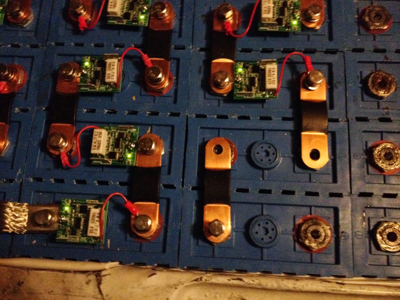
Finally, last night and this morning I interconnected all the cells.  There are three steps to interconnecting the cells.  First, I smear the terminal posts with a little anti-oxidant grease (NoAlOx or equivalent).  I then use an emery cloth to remove the oxide layer from both posts.  Then I put battery interconnects, MiniBMS modules, and M8 bolts/washers on.  For safety, I follow a routine when putting the interconnects on.  First, an M8 bolt is threaded through an interconnect to a cell which is not connected to anything.  It is not tightened, it just needs to be enough to keep that end of the interconnect from moving.  The interconnect in the lower middle has just had this done:


Next, I attach a MiniBMS module across the previous cell in the string, making sure to put the negative terminal on the negative post:


I tighten down both bolts finger-tight (I will later use an inch-lb torque wrench to finalize the connections).  With that done, I remove the M8 bolt that I previously placed:


This is done in this specific order to prevent unintentional short-circuits.  Without doing it in this order, it is possible that the interconnect you are working on will rotate over and close the circuit with the adjacent string.  This would be Very Bad - there are places on the battery string where 26 volts of potential exist between adjacent terminals.  The cells can deliver 1000A or more of current for a significant amount of time (tens of seconds).  A 26+ kW plasma event would be a very bad day, indeed (and you would not want to put your hand in there to disconnect anything!), leading to at least several destroyed cells and BMS modules, and at most a vehicle-destroying fire or even severe injury or death.  Obviously, I experienced none of those things. You will also note that my finger socket drive and socket are wrapped in electrical tape to reduce the chances of unintentional short-circuits.

With safety always in mind, I completed the interconnect of all the cells.  Here is the upper rear box glowing happily:

And the lower rear box, also happy:


During this process, I found one dead cell and one cell with a loose remote BMS wire.  This stymied me for the evening, but I was back at it this morning, finishing the front box:


and hooking up the BMS modules under the seats:


With 96 cells all happy, I hooked up the service disconnects, and measured the voltage at the junction box:


321.9 volts - about 3.35 volts per cell - perfect!  Next up, tuning the controller.

Custom Interconnects

I finally got a couple of weeks to work on the ElectroJeep.  First order of business was finalizing the battery layout and interconnects.  Here is the final layout:


You can download a PDF of the ElectroJeep battery layout here.  From left to right, the five battery boxes are named "front", "passenger's side under seat", "driver's side under seat", "upper rear", and "lower rear."  One significant change from the previous version is that the most positive terminal is now in the upper rear box rather than the lower rear box.  This was done to simplify the HV cable tangle at the front left of the lower rear box.

Note that there are several "odd" interconnects in the upper rear and lower rear battery boxes.  The task a couple of weeks ago was to actually manufacture the interconnects.  I created some patterns which I printed out on 8.5x11 paper.  The first is for the "turnarounds" - the two spots in the upper rear box which require a parity reversal on the cells' positive and negative terminals:


The PDF file for the turnarounds is here.  The second is for the "odd interconnects" - the L-shaped interconnects and the longer interconnect in the upper left corner of the lower rear box:


Again, the PDF for the odd interconnects is here.  I used double-sided tape behind each thing I wanted to cut out, stuck the pattern to a sheet of 0.02" copper, and cut them out with sheet-metal shears.  I then used my hole punch to punch out 5/16" holes, then stacked them together and used heat-shrink to bond them.  Here are the completed turn-arounds:


Each one is made from a stack of six cut-outs.  I designed them to be 22mm wide - basically, 0.9" - and 0.9" times 0.12" (the combined thickness) is 0.108 in^2, the cross-sectional area.  This is approximately the same as 2/0 gauge welding cable (0.105 in^2), which is what I'm using as the main cable size.

I also used a double stack of 1/16" by 3/4" copper straps in two places - between the EV display and a cell terminal, and between the CamLok inlet to the upper rear battery box.  This is 0.094 in^2, which is a little smaller than 2/0 cable (but about the same as the copper interconnects that come with the cells).  Here is the double strap behind the EV display:


You can also see the massive 400A 500VDC fuse to the left of the EV display, and the edge of a 30A 500VDC fuse holder on the right (which protects the charger wiring).  These are shown on the updated HV circuit diagram:


The PDF for the HV circuit diagram is here.  And, finally, here are the interconnects in their places (you can also see the CamLok connector in place in the upper rear battery box):


Next up (finally!) - interconnecting the cells.

Monday, September 2, 2013

BMS Wiring, Part 1

Today, I did some wiring toward getting the BMS in place.

First, I added some wires in the passenger's side of the rear compartment.  The green extension cord plug will eventually be the 120VAC battery warming power supply.  The green cord going into the cable gland and the silver thermocouple wire are also for the battery warming system (for the front box).  The white extension cord is for the BMS loop:


Here is the inlet for the battery warming plug.  I'm not going to do much more on this part for now (it's still pretty warm :-) but I wanted to get the hole-drilling and cable pulling out of the way:


The green, white, and silver cables go through the floor of the rear compartment to this LiquiTight conduit gland:


 The conduit proceeds forward along the wheel well...


...under the passenger-side rocker...


...and ends up in the engine compartment.  The silver thermocouple will go into the battery box; the white as mentioned will carry the BMS loop to these cells.


With the cabling out of the way, I wired up the BMS controller.  I went back and forth on whether to put this under the dash or in the rear - in either case, we needed some signals routed between front and back.  The deciding factor was that this placement is much more convenient to work on:


Here is everything all closed up and connected.  I tried plugging an EVSE in to see whether the kWh meter lit (and the charger light lit) but, no joy in Mudville tonight - the EVSE flashed a "line cord fault" indication.  I suspect I have the pilot and control lines reversed.  But for now, this *looks* pretty:


Here is the wiring diagram for the BMS.  I have not yet done the inter-cell connections (shown here in magenta, but I'll use white wires).  The PDF of this diagram can be found at this link.

So, this is probably as far as I get for the next few weeks - but I look forward to finishing the BMS wiring and trying a quick top-off charge cycle...

EDIT Sep 3 2013:  Swapping the PRX and PIL lines on the J1772 AVC1 unit fixed the problem!  I verified that all the other circuity is installed properly and working - connecting the cell loop (with no cells) causes the charge relay to engage, the 12V power supply is working, and everything seems happy.  The circuit diagram for that circuitry has been updated, as has been the previous post.

Sunday, September 1, 2013

Charger Control Electronics

"Well, we've tried every device and you still won't talk - every device, that is, except for this little baby we simply call 'Mr. Thingy.'":


OK, perhaps a little more explanation than this obscure Far Side reference is in order.  As mentioned before, with top-balanced lithium cells, you need to shut off charging current if any cell hits the high-voltage cutoff point (3.6V in my case).  Some chargers have ways to do this with a signal from the BMS.  But every charger is different.  I may want to change chargers some day, and in fact may want to experiment with an off-board charger for fast charging, so I created Mr. Thingy.  All Mr. Thingy does is provide a place to mount:

  1. A 40-amp solid state AC relay which can turn off the charger in a high-voltage-cutoff event
  2. The circuit board which handles the J1772 pilot and control signals
  3. The 12 volt power supply which powers both the relay coil as well as the "I'm plugged in, don't drive away you dummy!" light and interlock
  4. A kilowatt-hour meter to keep track of electricity used during charging
  5. Various plugs and receptacles to make switching between J1772 and a regular extension cord, and between the on-board charger and an off-board charger, convenient
All of this in an 8x8x4 inch box!  Here is the circuit diagram:


You can find the PDF of this circuit diagram here.  And here is the completed enclosure, mounted and attached:

For those who do not want to open the PDF, here is the note from that PDF explaining operation:

If the inlet 10-30P plug “B” is unplugged from the J1772, then the AVC1 will not have ground and will therefore not handshake with the J1772 EVSE, preventing any power from being present on the 10-30R receptacle labelled “A”. This is intentional.

When unplugged from the J1772, the 10-30P plug labelled “B” may be plugged in to a NEMA 10-30R receptacle for direct charging. The on-board charger can be unplugged from the 10-30R receptacle labelled “C” and another charger plugged into it for higher-power BMS-controlled charging.

J1772 Inlet from Tucson EV has the 2.74k ohm resistor preinstalled between PRX and ground.

All high-current 240VAC power wiring is 10 AWG.

EDIT Sep 3 2013:  Per this post, this did not quite work initially - the EVSE indicated a "line fault" .  Swapping the PRX and PIL lines on the J1772 AVC1 unit fixed the problem!  I verified that all the other circuity is installed properly and working - connecting the cell loop (with no cells) causes the charge relay to engage, the 12V power supply is working, and everything seems happy.  The circuit diagram for this circuitry has been updated, and now matches this updated PNG:


Charger Inlet

Another standard that has emerged is SAE J1772 - a new standard for EV charger plugs.  It is safer - it uses pilot and control signals to ensure that there is no current flowing unless an actual EV is connected.  It is also becoming more widely available, with companies like ChargePoint providing pay-per-use charging stations.  The Jeep will be 1772 compatible.  To do this required quite a lot of hacking...

The inlet was much larger than the previous plug I used, so I had to rip out all of the old metal where the gas filler tube used to be:

I also ultimately removed the remainder of the metal around the base - it was spot-welded in about half a dozen places, so was fairly easy to remove.  I then fabricated new sheet metal to replace it - you can see the poster-board template I made on the right:


Here you can see the new sheet metal test-fit in place.  This will also provide more room for components in the rear compartment - the level "base" replaces the complicated angled sheet metal that enclosed the previous gasoline filler (seen in the first picture in this posting):


Here is the view from the outside.  This is a nice vertical piece of metal to attach the new inlet to:


 I painted it white, put exterior silicone-based adhesive liberally around everything, then riveted it in place:


And here is the new J1772 inlet under the gas lid.  Very nice, if I do say so myself!


Rear HV Terminals

As part of the conduit-routing process, I added new holes into the lower rear box.  There are three holes.  The leftmost is for the upper-rear-to-under-seat conduit; the center one is for the lower-rear-to-front most-positive cable, and the right one is for the front-to-rear most-negative (2 gauge) cable:


Here are the conduit ends in place:


And here is the assembly with cables and terminals in place.  The terminals are fiberglass, designed for this purpose, and provide a convenient place to connect the cells as well as the charger:


Side note: I've known about step drills for a long time, but this is the first time I'd ever used one (seen in-place in the drill to the lower right).  For drilling holes in 1/8" or less steel, it is fantastic - no more changing drill bits from 1/8 to 3/16 to 1/4 to 5/16 to 3/8 for every hole...  it "just works" (with a liberal application of cutting oil to help).

Orange is the New Black

Over the years since I started work on the ElectroJeep, EV standards have evolved which help provide safety for first responders.  The most prominent standard is "Orange is High Voltage" - this tells first responders to avoid those areas, and not to cut any orange cables.  This standard is why I have gone to orange 2/0 welding cable for most HV wiring.  It is also why I tried this:


I actually do not recommend this.  This is the conduit for routing HV cable under the Jeep.  I used Krylon "plastic paint" to spray it orange.  Sadly, the paint does not interact well with the conduit - it remained tacky for weeks, probably due to an interaction with the plasticizer which makes the conduit flexible in the first place.  This is why the conduit looks so mucked-up in this next picture - it picked up dust, dog hair, grease, and whatever else it touched.  But I put it in place nonetheless - dirty orange is better than no orange at all:


I also painted as many of the battery racks and covers orange as possible.  Here is the upper rear rack:


And here are the box covers.  I neglected to photograph the assembly of the upper rear cover (second from bottom in this photo) and under-seat covers (two small rectangles, second from top):


Here are the rear covers in place.  I'm very happy with how they fit - tight, but not too tight, which means the cells will be very snug and secure (you can also see the new 1/4" polyethylene sides I riveted into the upper rear rack):


Here is the front cover in place.   You may recall that this originally was going to be the bottom of a new rack - but I decided to use the original rack, and flip the box I made, so that the "bottom" became the "top".  I added some tabs so mesh with the original threaded rod mounting points in the rack.  The cover also bolts to the sides for added security:


Finally, here are the covers for the under-seat boxes.  The left and right covers are slightly different, since the boxes are slightly different, which is why they are prominently labelled: