Showing posts with label BatteryRacks. Show all posts

Sunday, October 13, 2013

Finishing battery box lids

I finished the battery box lids this weekend.  First, I found that the epoxy I used just did not have enough shear strength - the shear force I put on the hold-downs while I used a router to cut grooves for interconnects to pass under was enough to pop some of the hold-downs off the acrylic top.  So, it's nuts and screws for the hold-downs to augment the epoxy.  All of the screws and nuts are countersunk so that they don't have any chance of interfering with anything:


Next, I applied 3/16"-thick foam weatherstripping to the acrylic lids.  This is to provide some vibration resistance, as well as some resilience so that everything stays nice and tight under compression.  Here is the lower rear cover (you can see some of the gaps that I routed out in this picture as well):


Finally, I also applied the 3/16"-thick foam to the metal box tops.  Again, to reduce vibration and to keep everything tight when compressed with the nuts/bolts that hold this all together:


One last step before battery interconnecting - I need to add material to keep the cells in-place horizontally (they don't quite fill up the space that the former AGM-1280T batteries occupied).

Sunday, October 6, 2013

Battery Box Covers

Although a vacation interrupted progress on the ElectroJeep in September, it is getting very close to energizing the main HV circuits.  However, before that happens, I want non-conductive covers in place to protect against mishaps.  Since orange is the new black, I went with orange acrylic covers, with 3/4" by 7/8" clear acrylic blocks to hold the cells down by their edges.  Here are the hold-downs epoxied to the covers, resting in their respective racks:


The front rack is simplest - just 4 parallel blocks:


The upper rear rack is also fairly simple - 9 parallel blocks:


The lower rear rack is more complicated due to the different cell orientations.  There are 7 parallel blocks, and two additional blocks at 90 degrees to hold down the 7 cells at the front of the rack:


The final step will be to add self-adhesive foam between the blocks and the cells, and between the rack-tops and the covers - this is all to reduce vibration and to keep everything in compression.

The under-seat cells will reuse the polypropylene covers - there is not room on top of the cells for the BMS boards, so a simpler hold-down will work well.  However, I need BMS modules.  So, I reused two of the boxes I built for the old AGM BMS, and mounted 3 BMS boards in each one:


The bolts that the BMS is attached to do not go all the way through the box - there is an inner floor that they are bolted to.  The inner floor is then bolted to the outer floor to keep everything in place.

So - I think I can start interconnecting cells safely now.  And then to re-energize the controller, the DC-DC converter, the voltmeter, and the new charger...

Sunday, September 1, 2013

Building the New Front Box

I'm catching up on a posting backlog dating back over a year.   It all started on the 4th of July weekend 2012 with removing the old batteries:


I also pulled all of the racks and cabling, since I'll be replacing the cabling (with orange high-flex 2/0 gauge welding cable), and refurbishing or replacing the racks:


Next, I built the front box.  It holds 30 cells, and fits inside the original front rack:


I welded a new front upper rack.  Because lithium cells are lighter, I used 1/8" thick steel rather than the 3/16" of the old lead-acid racks and boxes.  I originally was going to replace the front rack, so I built a new rack for the bottom.  I decided later to just use the existing front rack, and flip the whole rack so that the "bottom" becomes the top - this will be detailed in a later post.  Here is the completed rack:


I then created the battery box box from polyethylene, 1/4", natural color.  I started by cutting a single piece which covers the bottom, front, and back of the box.  The piece is then "V" grooved so it folds.  This starts with marking the path where the groove should go, and then clamping guides for a router to cut the path:


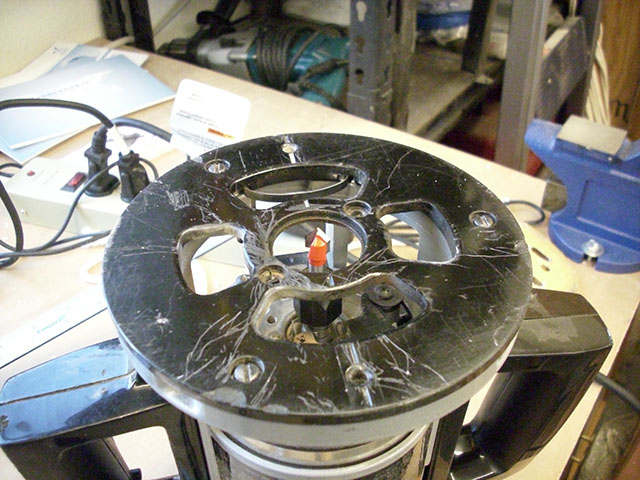
Here is the router, showing the "V" groove bit in place:


With the correct bit depth (not quite all the way through the plastic), it is a simple matter then to run the router between the guides, creating a nice straight groove:


Here is a test fit of the rack on the box, to make sure it fits:


And here is a test-fit of the cells.  I was originally going to use threaded rod to retain the cells in place, but it turned out to be impossible to get the rod through the sides when the rack and batteries are in place.  But the test-fit was with the threaded rod:


And that's what I got done on that weekend.  I also threw my back out as a result (what a drag it is getting old) which put a crimp (heh-heh) on further progress for over a year...


Tuesday, December 23, 2008

Pushing toward Final Assembly

I'll be away from the Jeep over the Christmas holiday, so I wanted to get as much done before I left as I could. So, I stayed up until 2:00AM Monday morning working on things. I did some potbox hackery to attach a threaded rod that will (eventually) be attached to the gas pedal. Basically, just a 10-24 machine screw with nylock nuts holding it to the potbox arm, and holding an angle bracket on (the nylock nuts are not tight on the angle bracket - it needs to be able to rotate). The threaded rod goes on the angle bracket, and will be pulled by the accelerator pedal as you depress the pedal:


I attached all the interconnects, flexi-cables, and PakTrakr connections to the lower rear box:


Between the lower rear box and the upper rear box, there are a CamLok connector and a 400A fuse. In keeping with my "no exposed 312V connections" rule, I put the fuse in an electrical conduit box. The red cable is very stiff, so I made the other side a "FlexiCable" connection to give me more wiggling options:


The red end of this cable attaches to the upper rear battery pack. It goes through an opening in the metal, so I added armor to protect it. I cut a chunk of leftover conduit to fit:


And then heat-shrink-wrapped it in place:


And there it is, attached. The interconnects and PakTrakr connections are also finished in the upper rear rack:


I then hooked up temporary interconnects between the upper rear rack and the under-seat racks, and between the batteries. Because I underestimated the amount of 4/0 cable, I had to order some more. It's not here yet, so I grabbed some 2-gauge battery cable and made up some two-wide cables as temporary interconnects (using 2/0 lugs). The circular area of two 2-gauge cables is about the same as 2/0 gauge cable - enough for my purposes for now (it will get replaced with 4/0 cable before I do any significant driving):


And then I finished the hookups in the engine compartment. It was getting late at this point, so I took some shortcuts - I have not heat-shrink-wrapped the interconnects, and I need to adjust the shortest ones so the batteries will line up properly. Also visible in this picture are the relay box, tie-wrapped in its final location in the upper left corner of the picture:


And here is the top on. Unfortunately, that front interconnect is still too tall, and the top does not fit all the way down. I will deal with that after vacation. For now, I'll live with a hood that does not quite close all the way (it latches but does not fully close):


And then it was time for bed.

Sunday, December 7, 2008

Interconnects, Hold-downs, and Conduit, Oh, My!

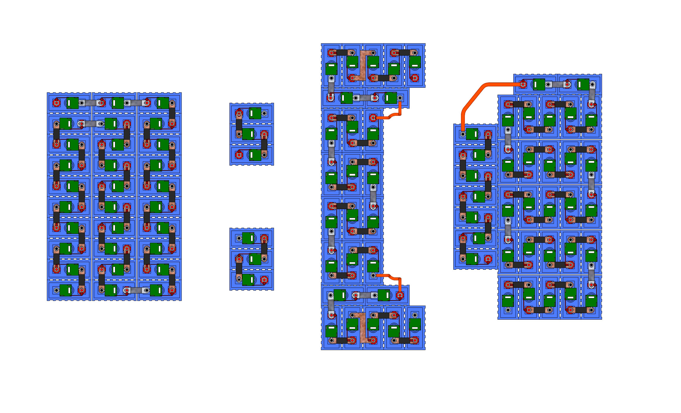
Another miscellaneous weekend. First, I tweaked the battery layout - the labels are the PakTrakr sequence that will show up, and gives a handy reference for talking about the batteries. The biggest tweak was battery B5 in the lower rear rack. I rotated it 180 degrees. This lets me use cable to do some of the interconnects. More importantly, it gets rid of the really close interconnect between A5-A4 and A6-A3 that the old design had. There was a potential of 84 volts between those two interconnects, and they were separated by only about an inch. Bad. Now, the biggest potential is 48 volts, found between D3 and D6 and between D2 and E2, in the front compartment. Only half as dangerous... Also, I indicate where the CamLock connectors will go, and have added a key so you can see how I did the bends in the interconnects (you want to add bends to your copper straps so they have a little "give" so they don't pry your battery terminals loose). PDF of the new layout replaced the old one, here.

And then, I got cranking on the interconnects. I tweaked my bending jig - I added a bolt to keep it aligned (and to keep it from falling apart every time I insert a new piece of metal). I also screwed the supporting angle irons into the wood. And, I added a rubber band around the bending irons to gently clamp the copper in place until I am able to place the big clamp. Here is the final bend being made on an interconnect with the adjusted jig:


And here is a large pile of bent interconnects. Only thing left is to drill them and install them. I don't pre-drill them because there are subtle differences in the hole-to-hole spacing.


Next, I finished the hold-downs - as in the lower rear rack, each battery gets a disc of polypropylene above it to firmly hold the battery in place. Most of the discs are bolted through the cover and into the steel hold-down. All bolts are nylon, to avoid any danger of electrical short circuits. Here is the completed upper rear rack:


Here is the front rack, from the bottom. You can see the 8 discs, and the countersunk nylon bolts:


Here's the front rack from the top:


And here are the under-seat batteries:


Finally, I mounted the conduit and the front-back AC cable. The front-back AC cable is needed because the relay that tells the controller "you're plugged in, don't let the idiot behind the wheel drive away" is in the front compartment. This cable is basically heavy-duty 10 gauge outdoor extension cord. I tie-wrapped it to the metal flange underneath the doors:


I also finished mounting the conduit. I used double tie-wraps at several strategic points. The driver's side conduit is a little tricky - there are brake fluid lines and power brake vacuum lines in this area, so I added a loop to the conduit to avoid them all (the tie-wrap that holds the loop in place is attached to a convenient hole in the rear seatbelt reinforcement):


Here is the passenger's side conduit. You can see the double tie-wraps keeping the conduit placed mostly protected behind the frame rail:


And now, bed time...

Friday, November 28, 2008

Misc Friday

Ahh, Black Friday. A day when every red-blooded American's thoughts turn to... electric conversions. Today was a day for some miscellaneous things I've been putting off for a while. First, I actually installed the "extra" battery mount (one of the first parts I welded). There are three 3/8-16 RivNuts inserted, and three 3/16" by 2" bolts through the rack into the RivNuts. The rack is held level above the sheet metal by three 1" spacers (this was required due to the slope of the fender right next to the mounting point). I also used RivNuts as the top hold-down attachment point:


Next, I made a top for the "extra" battery from polypropylene. Because this battery does not have a rack-style enclosure, I decided to get a little fancy and create a lip around the top to prevent curious fingers from accidentally contacting 312 volts. Basically, I just cut half-way through the box along the edges, and then liberally applied heat with a heat gun. And then, with sufficient force, the edges were bent down:


Next, I reinstalled the heater blower. First, though, I identified the main wire that is hot when the blower is active - it's the light blue wire here. I then added a pigtail blue wire on this so that I can control a relay which gates the heater contactor - I only want the 2000W heater running when there is air flowing:


With some help from KatC, I installed the blower assembly. Here is the view from the engine compartment. The two gold braided wires on the right are the main wires for the heater core. The purple and black lines are the vacuum lines which provide vacuum for the flapper box (TBD - how to hook them up....) And the blue wire is attached to the pigtail I just made:


Finally, I spent some time actually going over the factory service manual wiring diagrams in some detail. This allowed me to determine that some more of the factory harness can go (and should go - it just clutters things up). On the passenger's side, this harness goes to the EGR solenoid, the fuel pump relay, and the "B+" relay (basically, a relay controlling a time delay shutdown circuit). None of those are needed for ElectroJeep, so this whole harness gets guillotined:


On the driver's side, this whole harness which emerged from the bulkhead was entirely dedicated to controlling the gas motor. So, it got chopped. Here you can see the final electrical tape wrapping - basically, each wire gets folded back on itself about 3/4", individually wrapped with electrical tape, and then the whole mess gets taped together:


Tomorrow - weather permitting - I'll reinstall the front rack, finish its holddowns, and start working on battery interconnects (!).

Wednesday, November 26, 2008

Finishing Lower Rear Box Hold-Downs

The last pre-Turkey-Day thing I did was to finish the cover / hold-down. I cut 8 2.5" discs of polypropylene, and countersunk them to install 1/4-20 nylon screws:


I drilled holes through the top (and through the hold-downs where appropriate) and put the bolts on - note - nylon needs to be finger-tight only (I blew up one bolt making it more than finger tight):


Other things evident in this picture but not previously blogged:
  • I cut and installed the 1/8" polypropylene for the sides of the upper rear box
  • I cut, drilled, and painted the hold-downs for the upper rear box (from 3/16" bar stock)
  • I cut and installed the top for the upper rear box
It's getting *very* close to the final battery hookup. I need to:
  • Finish installing the heater (so I can mount the front rack permanently)
  • Permanently install the "extra" battery rack (one of the first parts I welded!)
  • Finish the upper rear, under-seat, front, and "extra" tops/hold-downs just like this
  • Cut lots and lots of 1/16" by 1" copper strap for the interconnect (each interconnect will consist of *three* such straps to allow high amperage to flow without excess heat)

Seat Boxes, IV

I also worked on the under-seat batteries. First, I cut, drilled, and painted a hold-down bar (made of 3/16" bar stock). I also installed threaded rod to hold it down (and a 3/8-16 RivNut in the middle). One note on the threaded rod - it actually goes through the 1/8" angle stock and through the Jeep's sheet metal. Unfortunately, there was not a good flat spot to attach the 3/8" rod - at least, no place where it would stick straight up. So, I just bent it - bending it once should not weaken it (repeated bending would, of course). Here it is:

I cut tops from polypropylene, and drilled holes for the conduit between the two boxes:


Here it is, very nearly complete, with the conduit between the two batteries installed. You can also see the connector for the conduit from the rear rack at the top of the picture, and the connector for the conduit to the engine compartment at the bottom of the picture:


One note - always consult your plans as you cut. You might note that there are *two* cutouts on the box at the bottom of the picture - I had put the batteries in backwards, and cut the openings based on the incorrect orientation of the batteries. As I consulted my plans, I discovered my error, and cut new openings. Not a big deal - but - measure twice, cut once continues to be true...

Sunday, October 19, 2008

Misc Parts

This weekend, I finished up some of the miscellaneous things that needed doing. First, I removed the front rack and the driver's side support. I did this because I needed to build the mount for the power steering pump (as seen below). I also need the rack out of the way to remove the heater core, and it will make a lot of the 12V wiring simpler.

With the front rack out, I cut a notch in one of the vertical supports to ensure that the steering rod will always clear it:


I built the mounting for the power steering pump:


I inserted a 3/8-16 rivet nut as the lower attach point for the power steering pump mount:


And I welded the controller mount. I then painted the controller mount, the power steering pump mount, and the two DC-DC converter mounts:


Not shown, but I also took the opportunity to caulk around the under-seat battery boxes to prevent leaks.