The ElectroJeep has been a little idle as a project as I've been engaged in other things - such as upgrading the
Volt914 to 216V. However, with that out of the way, I've returned to it. If you remember, the BMS I installed originally was a PakTrakr (scroll to the bottom of
this page) with
Zener diode regulators. This sort of worked - but I was very nervous about putting full amps into the batteries, and the PakTrakr has the unfortunate side effect of draining the first in its string of 6 or so batteries. Not a good combo - several of the batteries were getting seriously out-of-balance, and the Jeep was sitting at 325V after a "full" charge.
So, I finally got around to replacing that system with a much better one, based on Rudman Mk3 regulators from
Manzanita Micro:These are designed to connect to each battery. In addition, they are connected to each other and to the PFC-20 (soon, PFC-30) charger to tell it when the battery is getting full. I installed the older analog model on the
Volt914 - the digital model lets you adjust the cutoff voltage dynamically, so I can actually charge the batteries correctly no matter the temperature.
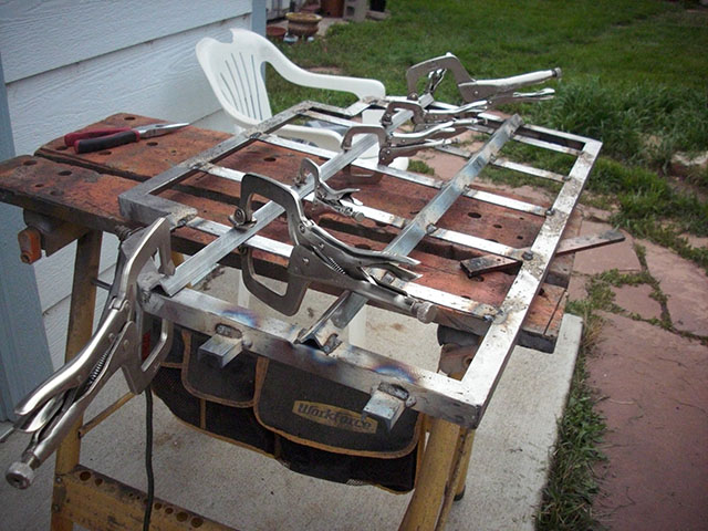
The first thing to do was to make plastic boxes to keep the regulators protected. I started by cutting little corner chunks out of 1/2" polyethylene:
The idea is to weld together a box around these corners, which themselves become the mounting points for the transparent covers. I had previously obtained a plastic welding kit, which included the welder as well as various plastic welding rods (including polyethylene):
The boxes are of various dimensions, to hold different numbers of regulators. After calculating dimensions, I cut out the basic shapes from 1/4" polyethylene, and then cut bending tracks where the sides will fold up:
Four of the corner pieces go on each box. Here is one box, from the inside (before folding). Note that the corner chunks of the envelope have been removed here:
Here is the same box from the outside. I used 3/4" self-tapping screws (although I also drilled pilot holes). These screws are mostly to hold it together long enough to weld, although I never bother removing them:
The next step is to fold up all four sides and then screw them to the corner pieces:
The corners are then welded (and a bit of the long fold is welded as well, to add strength). Holes are drilled for cable egress, and smaller holes are drilled for the nylon screws which hold the regulators securely in the boxes:
And here are all seven completed boxes. One of them has some of the wiring attached:
The next step is to attach the connectors which will allow me to easily connect and disconnect the boxes for servicing. I use WeatherPak connectors - you can see them here grouped in the order in which they will be used in each box. In addition, you can see the 12-gauge wire I use to hook the batteries to the regulator. 100 feet of red and 100 feet of black were just plenty:
Here is all the wiring complete. I call this the "14-armed monster". If you look closely, you can see that the internal phone-wire style interconnects are also attached:
Next step is to construct connectors to attach to the batteries. A note on safety: before connecting the ring terminals to the battery bolts, it is safest to insert the pins into the shells - this prevents them from rattling around and perhaps making a circuit with another battery post:
Another note on safety - all the tools used near the batteries have been wrapped in electrical tape within an inch of their life. Note that there are still a few exposed metal places - particularly on the torque wrench - to prevent from interfering from the operation of the tool. Nothing is 100% safe, but every millimeter that is covered in tape is a millimeter that will not close a high-amperage circuit - I've
experienced that once, I never want to try it again:
So, with the process established, it is just step and repeat. Here is the lower rear battery box all wired up. You can see that each battery has both a red wire and a black wire. In the connector, the red and black wires alternate - this makes it easier to verify that they are correctly paired, and less likely to make a catastrophic mistake:
Here is the upper rear battery box, complete. Note that, before connecting the batteries to the boxes, I use an ohm-meter to verify that the connections go where I think they go - better safe than sorry:
Here are the under-seat batteries and their regulators:
And here are the front batteries and regulators:
The next step was to interconnect the regulator boxes with the 6-wire phone cord, and then verify their correct hookup by flipping DIP switch 6 on the charger and turning it on (with the amp knob turned to zero). Here are the rear regulators - the yellow lights indicate that they are all talking on the regulator bus:
Here are the under-seat regulators glowing:
And here are the 8 front regulators in the big box glowing:
And finally the lonely little battery at the end of the string with its regulator glowing:
With the regbus wiring verified, and the boxes closed up again and everything connected to enable the full 312V circuit, it is time to charge! For a test point, I disconnected the DC-DC converter and used its HV input lines as a convenient place to plug in a multimeter:
In the rear, I used a clamp-on DC ammeter to verify the current going in to the pack (the new PFC-30 has a built-in ammeter so this step will not be needed):
You'll note that the ammeter says "10.02" - that's not a full load. As I mentioned before, the batteries were significantly out-of-balance. So, a few of them got to full charge first. The most problematic were two batteries in the front compartment. Here you can see me blowing a fan on them to cool them down - this helps the regulator dissipate excess current more effectively. The overheating regulators are the ones with the glowing purple lights:
There were a few regulators in the back that also got hot, so I took the covers off and applied significant airflow to them. Note the hot air gun at the lower right - it was turned to blow cool air, not hot air:
A combination of lots of cooling air along with turning the charger down to output 3 or 4 amps finally allowed things to settle down and charge. Here you can see the green lights of several regulators in the back glowing - this means the regulators are bypassing current but not overheating:
At this point, the pack is nearing full. We've reach 371 volts or so, and the constant current phase is over. Now the charger switches over to constant voltage, ramping down the amps as it counts down on a timer. I set the timer close to the max - the batteries seem to require it. You do not want to cut off this phase prematurely, or the batteries will not be charged. Here is the voltmeter monitoring the constant voltage phase:
Finally, at the end, the timer completed and everything was done. The green, yellow, and blue lights on the charger are normal, and indicate that everything finished OK:
And here is the pack the next morning. 333.5 volts is by far the highest the pack has achieved in a year, and a significant improvement over the 325 volts or so it was getting before. This is an average of about 12.8 volts per cell, which is where it needs to be:
This process will need to be repeated a few times before the batteries stay more balanced. To facilitate that, I will be installing fans on all the regulator boxes (so I don't have to grab all the household fans every time I want to charge). In addition, I will soon be upgrading from the PFC-20 to the PFC-30 charger. This will allow me to charge at up to 30A input at 240VDC - which translates to allowing me to charge at 16A at 370VDC - 16A is the recommended C/5 charge level of the AGM-1280T.
This process took several hours per night over the course of a week. And I'm exhausted. But it is nice to be making forward progress again.