Monday, April 28, 2014

New Vacuum Pump

Nearly 5 years ago, I installed ElectroJeep's power brake vacuum pump.  It was a noisy little beast, and it always irritated me.  Some time in the past 5 years, I got a new, quieter pump to replace it - the MES 70/6E2 - but I never got around to installing it because it was taller than the old pump and would not fit in the same spot.  However, with the new LiFePO4 layout, I had a blank spot where one of the 26 old AGM batteries had gone.  A perfect spot to mount both the new pump as well as the power steering reservoir:


The pump is mounted on little anti-vibration feet, and is much MUCH quieter than the previous pump.  I hooked it in to the original vacuum reservoir, which includes an adjustable vacuum sensor switch:


And now I have power brakes - in style!

Saturday, April 26, 2014

100 Lithium Miles

Today, the ElectroJeep celebrated 100 miles of Lithium!  I've used it as my daily driver all week.  I'm very happy with it.  I've been keeping track of the power required to charge it - here is a chart as of this week:


You can see the spreadsheet data here - I'll update it every day that I drive.  From this data, I can see that my target of "50 miles range" will be met, easily (at least at spring/summer temperatures).  I'm getting about 380 Wh/mi range (I had guessed "400"), with a 1.4 kWh "per-charge" overhead.  Given that this is a 30.7 kWh pack, that translates directly to a 56 mile range at 70% depth-of-discharge. That would be an 80 mile range at 100% DOD, but that runs the significant risk of killing the pack.  Not going to tempt fate.


Sunday, April 20, 2014

EMW EV Dashboard

I had previously installed a sender board for the EMW EV Dashboard Android app:


Today, I hooked up the BlueTooth module and got it calibrated and running to my taste.  Here is a screen shot:


It shows current (both analog and digital), voltage (both analog and digital), charge (both analog and amp-hours remaining), and power being consumed.  I drove about 5 miles around the section block - the app worked really well.  And it looks like my estimate of roughly 50 miles range is going to be accurate - I consumed about 7 Ah for the 5 mile range.  70% DOD from 100 Ah is 70 Ah - and 70 Ah * 5 Mi / 7 Ah = 50 miles.  To one significant digit.

It's a vehicle again!

With everything wired up and functional, it is time for a test drive.  So, without further ado - the ElectroJeep rides again!


It's riding pretty high, so I will probably ratchet back the lift kit to avoid undue stress on the transmission.

BMS Cell Loop Interconnected

With the cells interconnected and the BMS modules installed, the critical final step before energizing the whole system is interconnecting the cell loop.  Here is the schematic - the interconnects are highlighted in yellow on the diagram:


The PDF of the BMS wiring is here.  I had previously built 80-some short interconnects for the tops of the cells.  These went on pretty easily.  First, the front box:


Next, the upper rear box:


And finally, the lower rear box:


With all the interconnections in place, I did the final torquing of the terminal bolts using my inch-lb torque wrench (9 N*M or roughly 80 inch-lbs per the specs):


You'll note it is largely wrapped in electrical tape - safety first!  Finally, I hooked up the previously-installed inter-battery-box cabling and plugged the charger in - and it made it safely to its first charge:


So, with wheels turning and charger functioning - it is a car!  Up next - a test drive.

Sunday, April 13, 2014

It's Alive (again)!

With all of the batteries interconnected, I finally turned the controller on for the first time in nearly two years.  I was pleasantly surprised to see that it came right up.  I hooked up my little Windows XP notebook (kept for just this purpose) and tweaked the settings for the new voltage levels:


The four key parameters I changed were:

  • EE2NoAccelBat - this is the voltage level below which no current should be drawn.  I set it to 2.8V per cell, or 268.8V total
  • EE2NoRegenBat - this is the maximum voltage above which no regenerative braking will occur.  This is set lower than the charge current to keep the cells from overcharging and causing the MiniBMS to haz a sad.  I set it to 3.4V per cell, or 326.4V total
  • EE2PSHighBatVoltage - I don't know what this is for, but I set it to the charge cutoff voltage of 3.5V per cell, or 336V
  • EE2PSLimitBatVoltage - I don't know what this is for, either, but I set it to the maximum I ever want to see on these cells, 3.6V per cell, or 345.6V total
With the parameters established, I put the Jeep in neutral, then turned the handle to "drive enable."  Pushing the throttle spun the motor!  So I put it in first and drove forward a couple of inches.  Victory!

It's not ready to drive around the neighborhood, yet - I need to finish the BMS wiring and do some other miscellaneous mechanical / cosmetic work.  But this is a significant milestone.

Cells Interconnected!

Before interconnecting the cells, I spent some time yesterday making sure everything was ready.  I added orange flex-guard around all of the exposed HV cables, and modified my power junction box to be more easily accessible (but still covered to keep curious fingers away):


I also mounted the 10A fuse for the DC-DC converter in an electronics box:

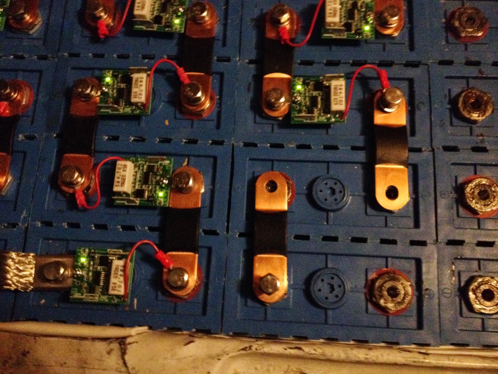
Finally, last night and this morning I interconnected all the cells.  There are three steps to interconnecting the cells.  First, I smear the terminal posts with a little anti-oxidant grease (NoAlOx or equivalent).  I then use an emery cloth to remove the oxide layer from both posts.  Then I put battery interconnects, MiniBMS modules, and M8 bolts/washers on.  For safety, I follow a routine when putting the interconnects on.  First, an M8 bolt is threaded through an interconnect to a cell which is not connected to anything.  It is not tightened, it just needs to be enough to keep that end of the interconnect from moving.  The interconnect in the lower middle has just had this done:


Next, I attach a MiniBMS module across the previous cell in the string, making sure to put the negative terminal on the negative post:


I tighten down both bolts finger-tight (I will later use an inch-lb torque wrench to finalize the connections).  With that done, I remove the M8 bolt that I previously placed:


This is done in this specific order to prevent unintentional short-circuits.  Without doing it in this order, it is possible that the interconnect you are working on will rotate over and close the circuit with the adjacent string.  This would be Very Bad - there are places on the battery string where 26 volts of potential exist between adjacent terminals.  The cells can deliver 1000A or more of current for a significant amount of time (tens of seconds).  A 26+ kW plasma event would be a very bad day, indeed (and you would not want to put your hand in there to disconnect anything!), leading to at least several destroyed cells and BMS modules, and at most a vehicle-destroying fire or even severe injury or death.  Obviously, I experienced none of those things. You will also note that my finger socket drive and socket are wrapped in electrical tape to reduce the chances of unintentional short-circuits.

With safety always in mind, I completed the interconnect of all the cells.  Here is the upper rear box glowing happily:

And the lower rear box, also happy:


During this process, I found one dead cell and one cell with a loose remote BMS wire.  This stymied me for the evening, but I was back at it this morning, finishing the front box:


and hooking up the BMS modules under the seats:


With 96 cells all happy, I hooked up the service disconnects, and measured the voltage at the junction box:


321.9 volts - about 3.35 volts per cell - perfect!  Next up, tuning the controller.

Custom Interconnects

I finally got a couple of weeks to work on the ElectroJeep.  First order of business was finalizing the battery layout and interconnects.  Here is the final layout:


You can download a PDF of the ElectroJeep battery layout here.  From left to right, the five battery boxes are named "front", "passenger's side under seat", "driver's side under seat", "upper rear", and "lower rear."  One significant change from the previous version is that the most positive terminal is now in the upper rear box rather than the lower rear box.  This was done to simplify the HV cable tangle at the front left of the lower rear box.

Note that there are several "odd" interconnects in the upper rear and lower rear battery boxes.  The task a couple of weeks ago was to actually manufacture the interconnects.  I created some patterns which I printed out on 8.5x11 paper.  The first is for the "turnarounds" - the two spots in the upper rear box which require a parity reversal on the cells' positive and negative terminals:


The PDF file for the turnarounds is here.  The second is for the "odd interconnects" - the L-shaped interconnects and the longer interconnect in the upper left corner of the lower rear box:


Again, the PDF for the odd interconnects is here.  I used double-sided tape behind each thing I wanted to cut out, stuck the pattern to a sheet of 0.02" copper, and cut them out with sheet-metal shears.  I then used my hole punch to punch out 5/16" holes, then stacked them together and used heat-shrink to bond them.  Here are the completed turn-arounds:


Each one is made from a stack of six cut-outs.  I designed them to be 22mm wide - basically, 0.9" - and 0.9" times 0.12" (the combined thickness) is 0.108 in^2, the cross-sectional area.  This is approximately the same as 2/0 gauge welding cable (0.105 in^2), which is what I'm using as the main cable size.

I also used a double stack of 1/16" by 3/4" copper straps in two places - between the EV display and a cell terminal, and between the CamLok inlet to the upper rear battery box.  This is 0.094 in^2, which is a little smaller than 2/0 cable (but about the same as the copper interconnects that come with the cells).  Here is the double strap behind the EV display:


You can also see the massive 400A 500VDC fuse to the left of the EV display, and the edge of a 30A 500VDC fuse holder on the right (which protects the charger wiring).  These are shown on the updated HV circuit diagram:


The PDF for the HV circuit diagram is here.  And, finally, here are the interconnects in their places (you can also see the CamLok connector in place in the upper rear battery box):


Next up (finally!) - interconnecting the cells.