Monday, September 29, 2008

Polypropylene covers, I

For electrical insulation and keeping water, dust out of the battery racks, each will have a polypropylene cover. I purchased some 1/4" thick polypro at a local plastic shop. I used this blade on my circular handsaw to cut it up (I found that Sharpies mark on it acceptably for guidelines):


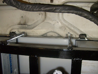
Here is the front cover in place, with the hold-down bolted down over it:


Here is the view of it from below, with the hood closed. Very, very close to interfering - but it does not interfere:


This is a closeup of the threaded rod going into the top hold-down as well as the outlet hole for the 4/0 welding cable. The holes that the 3/8" rod go through are 7/16" in diameter to provide for just a little "slop" in getting the rack on (without that, you pretty much have to get all 6 holes lined up perfectly then drop the top on exactly vertically):


I also cut the cover for the lower rear rack. Here it is, with the hold-downs placed on top of it for effect:


I have a few more holes to drill in the upper rear rack and the under-seat racks, and then it's time for paint for them. Getting very very close to wiring time...

Sunday, September 28, 2008

All Done With Welding?

Today I did what I think is the final welding on battery racks / boxes / hold-downs. First, I finished the hold-down for the front rack. Here is what it looks like in Sketchup:

The protrusions are of two kinds. The first (6 of them) is a place for the threaded rod to attach to. The second (2 of them) is kind of a protective "cover" for holes in the rack to allow the 4/0 welding cable to enter/exit the rack. To make them, I started with 1.5" by 1.5" box tubing (3/16" walls):


I cut each piece in half, either straight or diagonally:


And then welded them in to place:


Here's the hold-down balanced on top of the threaded rod (on top because I have not yet drilled the holes for the rod to go through):


I also did the final welding on the upper rear rack. I created a cube missing two walls out of 1 1/4" by 1 1/4" (1/8" thick) angle stock:


I then welded that on to the upper rear battery rack. This also is a protective "cover" for a place where cable exits the box. It also, not coincidentally, reinforces the horizontal support so that a hole can be made in it.

I also welded on the threaded nuts for the hold-downs to screw into:


There are three remaining things to do on the racks:

  1. Drill any required holes
  2. Paint
  3. Install

Saturday, September 27, 2008

Front Hold-Down, I

Today I worked on the hold-down for the front battery rack. First, I cut 1 1/2" by 3/16" angle stock to size and welded it together (it's basically identical to the dimensions of the base of the front rack):

Next, I test-fit it over some batteries in the front rack. I think I knew this was going to happen, but I had managed to forget about it - the hold-down interferes with a lip projecting from the firewall:

Here is the area of interference outlined with a Sharpie:


I'm not sure how structural this part is. But, just in case, rather than removing it, I just cut it a little and bent it up out of the way - the bent part should still provide some vertical stiffness:


As you can see, the hold-down no longer interferes with the firewall protrusion:


So, here is the hold-down in place. There is still a fair amount left to do - I need to put the crosspieces on, and I need to add the flanges where the bolts will clamp down on the 3/8" rod. Also, I need to cut two outlet holes in the front of this hold-down to allow the 4/0 welding cable to come in/out of the rack.


With the hold-down in place, I can now shorten the 3/8-16 rod. I left it 1/2" longer than the top of the hold-down (to account for 1/4" of polypropylene and 1/4" of threads for the nut to grip). And now, the true acid test - closing the hood. Unfortunately, it failed. So, I borrowed one of my daughters' lipsticks and marked the rod/nuts:


Here is where that touched the hood. I circled it on the left and right with a Sharpie to make it easier to see:


And here are the holes I drilled out so the hood can close:


With all that, here is the closed hood with the top in place:


Thinking back on it, I suspect what happened with my previous test was that I assumed that the outside corner was the most likely interference point. I did not think of the rod sticking up...

Upper Rear Rack,II

This week I found a few spare moments to finish the upper rear rack by adding a cage around the top which will hold polypropylene sheets to enclose the batteries. Here is the design done in Google Sketchup (PDF version here):


I cut the pieces mostly out of 1" by 1/8" bar / angle stock - the cage is not really structural (other than under tension to hold the top on):


Here it is, all welded together:


And placed in its location:


Still a couple of things to do to this rack: it needs the nuts welded on for the top hold-downs; it needs a hole cut to allow the 4/0 welding cable to exit the box; and, of course, it needs to be painted.

Sunday, September 21, 2008

Final Battery Layout!

Well, with the racks all basically designed and nearly built, I believe I can declare victory over the battery layout. Here is a picture of it:

You can find the PDF file here. The orange interconnects will be copper strips. Each interconnect will consist of a stack of 3 1" by 1/16" strips. This gets a cross-sectional area of 0.1875" which compares well with the cross-sectional area of 4/0 welding cable (which is 0.166"). The strips will be cut longer than shown and then creatively bent to allow for flex. Each strip will be heat-shrink wrapped for insulation, and then the three will be stacked on top of each other and screwed in to the battery (with a generous dollop of Noalox all over the place).

Here is a picture for example of the battery interconnects that Electro Automotive did for the Volt914 / VoltsPorsche AC. The ElectroJeep interconnects will be different, since the batteries do not have "L" terminals but rather screw-in terminal posts:


As a reminder, here is the evolution of the ElectroJeep battery layout:

Version 1.0, January 2008:


Version 2.0, March 2008:


Version 3.0, July 2008:


There may be a few minor tweaks (the two diagonal interconnects in the lower rear battery rack, on the right side of the picture bother me - way too close even if insulated), but I expect this to be very close to the final layout.

Hey, Rocky, watch me pull an Electric Jeep out of my hat...

Lower Rear Rack, III

As I mentioned in the previous post, I got tired of lugging the rear rack / box around (it's very heavy). So, today was the day to permanently install it. First, I cut a notch in it and top-coated it with UV-resistant POR-15 topcote:


The notch is designed to avoid this bump in the back of the Jeep. Without cutting the notch out, this bump puts pressure on the rear of the rack, causing a pronounced "bowing in" effect:


Before installation, I cleaned up the rear compartment and rattle-can painted it white (both for cosmetic reasons as well as to avoid rust):


I lowered the rack into place, using a floor jack to keep it from dropping all the way down yet:


I did this because I need to put sealer around it. I used GE Silicone II, as used in the Porsche:


I gooped a very wide bead all around the hole:


Then lowered the rack in place, installed the bolts, and put the batteries into their final locations:

Note that the sheet metal is now bent down over the back of the rack. The batteries and cover still fit under this sheet metal. I was careful to fill any gaps with the silicone.

Next: work beckons once again, but I may find a few spare moments to build the second seat rack or perhaps to finish the upper rear rack.

Seat Boxes, II

Time to build the racks for the under-seat batteries. Getting accurate dimensions was tricky with the complicated curves under the seat. So, I cheated. I marked a hole the size of the battery box:


The front of the hole aligns exactly with the factory "drain plug" used during initial priming of the body - I knocked the plug out with a hammer (you can see the hole here). The outside cut of the hole is designed to be just about even with the "frame rail" beneath, to give the box extra security. I used a cutoff wheel on my grinder to cut the hole out (note the "flaps" - these stay attached and will be bolted to the rack):


And I test-fit the box in the hole. Just right. With the box in place (supported from below by a floor jack) I traced the contours of the hole on it.

With the box removed, I tweaked the contours to something reasonably easy to cut / bend / weld (you can see my first sketch of the upper part of the rack here):


With those measurements, I went inside and used Sketchup to design the complete rack. You can find a PDF blueprint here. This is a rendering with the box inside:


Here are the two side pieces cut, bent, and welded together, test-fit against the lines drawn on the box:


Here is the completed upper part of the rack, test-fit in the hole (this is a view toward the passenger's side from the driver's side):


Here is the completed rack with the box inside it. This is a very tight fit - the blueprints above were sized up a little to make it not quite so tight (so the second one I build should slide in more easily):


Here is the completed rack resting in its hole:


And here is a battery inside the box inside the rack:


Same thing, from below, to check for interference. This sags a little more than the actual mounting will, since it does not have bolts (or maybe rivets) attaching the rack to the sheet metal flaps:


Next task: installing the lower rear rack permanently (I'm tired of moving the rack around the garage...)

Friday, September 19, 2008

Seat Boxes, I

Last post, if you recall, I designed the seat boxes - here is the pattern, for reference:


As with the sheet metal for the lower rear battery box, I printed it out on several sheets of 8.5x11 paper, taped it together and cut it out (the holes in the middle are extra taping points):


Since I was making two identical boxes, I just clamped two sheets together and taped the pattern on top of the stack:


Here is one of them, cut out and sanded down all pretty:


The folds are kind of tricky. If I had sheet metal wider than 24" I would not have done the pattern this way - but this is the only way it would fit on a 24x48 sheet of steel. First, I folded the upper lip over (to make a sturdy and non-sharp edge around the top). Next, I folded the "envelope flaps" partly over:


More folding. Here comes the tricky part - you need to fold it all up just about simultaneously or it does not mesh properly. Even as it meshes properly, there is some final hammering / pushing / bending needed to get it into box shape:


Here it is, completely folded and ready for welding:


To weld, I first used various clamps to keep the flaps down completely flat against the walls:


Here is KatC, spot-welding one of the boxes:


Given that this will have a complete rack supporting it, spot-welds are more than adequate. I will paint these and then put seam sealer around the edges to keep water out:

Next up - more welding on racks...