Tuesday, December 23, 2008

More 12V hackery

I've actually been so busy on the Jeep the last couple of weeks, I've not had time for blogging. The next few posts will make up for that...

First, I did some work on the 12V relay box. I made the cables that will attach the box to the DMOC controller and to the dash instrumentation. The DMOC cables use GM WeatherPack connectors - which are very handy things, well-sealed and robust.

You start by collecting your pin, seal, and crimper:


Push the wire through the seal, and crimp the pin on to the wire and on to the seal:


Push the seals through the connector, close the end, and you're all done. About 1 minute per pin once you get the feel of it. Here is the relay box with its cables attached (the ones at the lower left connect to the DMOC, the ones at the upper right connect to the dash instrumentation).


After looking closely at the wiring diagram, and after deciding to get a 120/240VAC to 12VDC power supply to integrate into the system, I realized two things. First, the glass fuses were pretty much all for the AC power supply and relay. Second, with those fuses gone, there was plenty of room in that box for the heater contactor. So, here is, I believe, the final 12V diagram:


And here is the assembled box, integrated in (the dash wiring is not complete, nor is the heater wiring, but the box is hooked up to the keyed 12V (yellow wire on the left), ground (black wire), and the DMOC:


The current wiring diagram PDF is, as always, here.

Tuesday, December 16, 2008

Odds and Ends

I also test-fit my copper interconnects, and found I had made some of them 1/8" too tall (and a few of them are marginal in their length). Fortunately, changing the 90-degree bends to 75-degree or so bends dropped the height just enough and increased the length just enough:


Also, this Saturday I got started on getting the transmission put back together for real - I hooked up the wires, reattached the tail cone (including a gasket), and read up on replacing the U-joints. That's as far as I got, though, since winter has arrived with sub-zero temperatures, so I'm working on "things that can be accomplished inside" for the moment.

Monday, December 15, 2008

Controller Power Input Cables

Remember the Cam-Lok cable connectors? I finally installed a couple of them. I built the cables that are the final terminal into the DMOC controller. As you may recall, 4/0 cable is too thick to pass through the strain relief fittings on the controller. After debating several options, I decided to use 3/0 cable for this section. I got a few feet of red and a few feet of black and went to town.

First, I cut the end of the Cam-Lok connector so it snugly fit over the 3/0 cable:


Next, I slimed the cable with electrician's cable-pulling slime:


Then I pulled the cable through the housing:


I stripped the end the required length (somewhat longer than a crimped lug requires):


Then I wrapped the copper shim around the end, and tightly wrapped the copper strain relief wire about 1/2" below the stripped end, twisting it and laying it against the shim:


I then installed the brass connector and torqued the screws down to spec:


A touch more slime, and I pulled the shroud over the connector and inserted the retaining screw. All done!


I did the black cable too:


There is a problem, though. 3/0 gauge lugs will *not* pass through the strain relief bushings. And they need to - the tolerance on the DMOC is too tight, the ends of the lugs need to be inside the bushings. Also, 3/0 lugs are too wide - I would need to cut the end of one down (as shown in sharpie on the lug to the left). 2/0 lugs, as shown on the right, are "just right".


So, I clipped a few of the fine wires out so the remaining wires would fit snugly in a 2/0 lug, and crimped it and heat-shrunk it (after making sure the bushings were already on the cable *above* the lug connection - oriented properly). A little application of slime let me slide the bushings over the whole thing:


And here are the completed cables test-fit (but not bolted on yet):


Despite the fact that the overall system uses 4/0 cables and lugs for everything, I think this short 18" stretch of 3/0 cable funneled into a 2/0 lug won't affect performance too severely - it is a short distance, and the resistance delta between 3/0 cable and a 2/0 lug at this distance is nearly too small to measure. In fact, I took my multimeter to identical lengths of 4/0 and 3/0 cable, and I could not find any difference in the measured resistance.

Making FlexiCable

There are a couple of problematic connections in my battery layout. Particularly, the connection between A4 and A5 in this diagram is tricky. I tried making a traditional cable, but the 4/0 cable I'm using does not flex enough. So, I improvised. Looking up the specs on welding cable, I found that three 2 gauge cables are nearly identical to one 4/0 gauge cable, both in circular area as well as specified ampacity. So, I cut and stripped three lengths of 2-gauge cable (here shown next to 4/0 gauge lugs):


I firmly taped the three together, then fit 4/0 lugs onto them...


...then crimped the snot out of them (after all, who wants snotty cables?):


Here is the crimped flexi-cable:


And here is me flexing it one-handed. I could not come close to flexing the 4/0 gauge cable like this:


I double-heat-shrink-wrapped the ends:


And here it is, snug in its location:

Sunday, December 7, 2008

To-Do List

I also made a list of those last things that need to get done to get the ElectroJeep on the road.

Things that must get done:
  • Finish 12V wiring
  • Hook up power steering
  • Hook up power brakes / heater controls (other vacuum?)
  • Hook up e-brake
  • Install potbox (relocate throttle cable?)
  • Hook up controller wiring harness
  • Finish transmission:
    • Put gasket on tail cone
    • Replace U-joints
    • Torque to final specs
    • Hook up wiring
    • Hook up clutch hydraulics
    • Fill / bleed clutch hydraulics
    • Fill with tranny / t-case fluid
  • Install gauges / controls
    • Including wiring through to engine compartment
  • Torque suspension to final specs
  • Bleed brakes
  • Install battery interconnects
  • Cut & install long 4/0 cables
  • Install PakTrakr
  • Finish charger wiring
  • Shorten 3-phase cable
  • Hook up controller 312V cables
Things that would be nice to have done, but are not required:
  • Install manual t-case cable
  • Replace rotors, drums, and pads

Interconnects, Hold-downs, and Conduit, Oh, My!

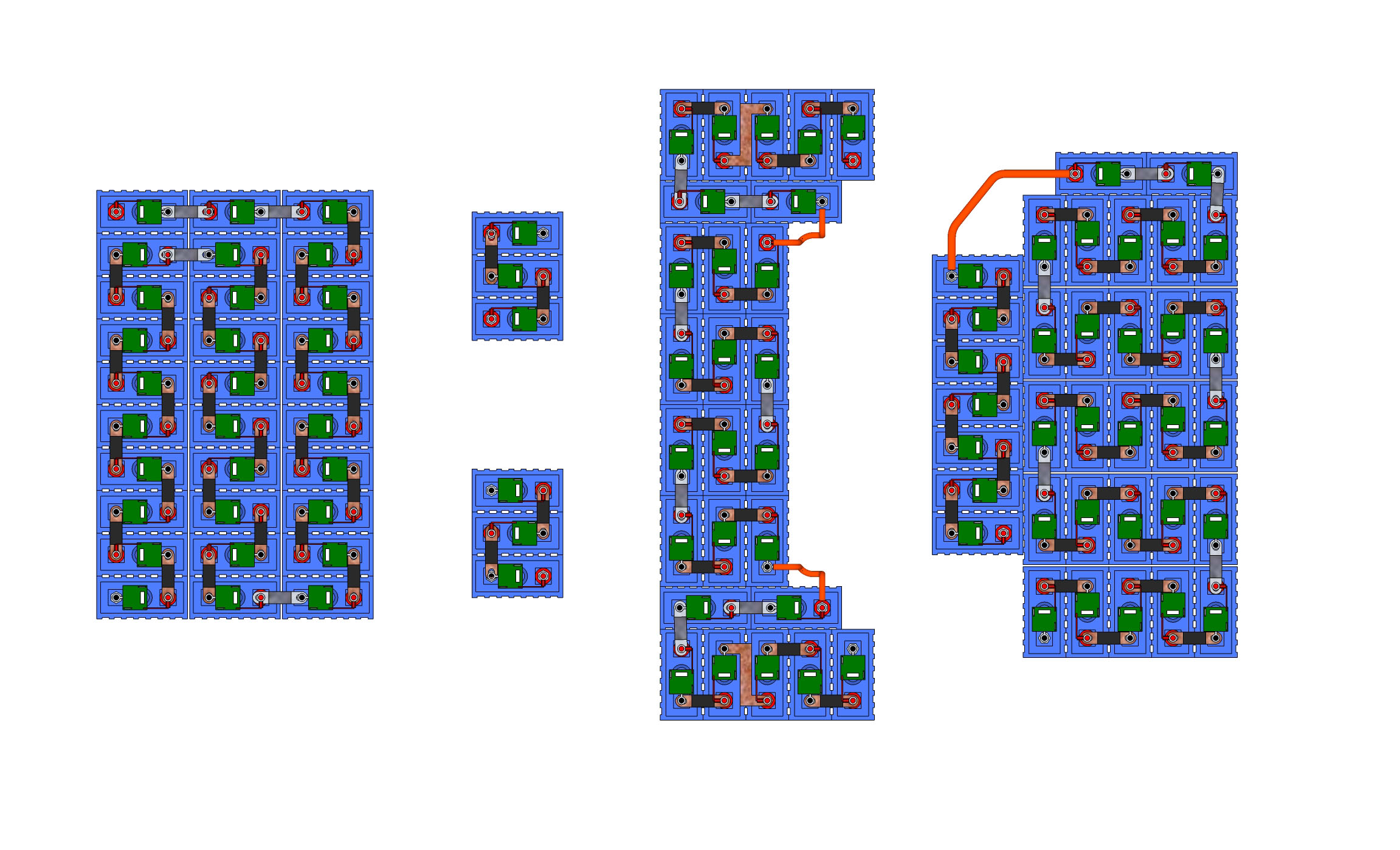
Another miscellaneous weekend. First, I tweaked the battery layout - the labels are the PakTrakr sequence that will show up, and gives a handy reference for talking about the batteries. The biggest tweak was battery B5 in the lower rear rack. I rotated it 180 degrees. This lets me use cable to do some of the interconnects. More importantly, it gets rid of the really close interconnect between A5-A4 and A6-A3 that the old design had. There was a potential of 84 volts between those two interconnects, and they were separated by only about an inch. Bad. Now, the biggest potential is 48 volts, found between D3 and D6 and between D2 and E2, in the front compartment. Only half as dangerous... Also, I indicate where the CamLock connectors will go, and have added a key so you can see how I did the bends in the interconnects (you want to add bends to your copper straps so they have a little "give" so they don't pry your battery terminals loose). PDF of the new layout replaced the old one, here.

And then, I got cranking on the interconnects. I tweaked my bending jig - I added a bolt to keep it aligned (and to keep it from falling apart every time I insert a new piece of metal). I also screwed the supporting angle irons into the wood. And, I added a rubber band around the bending irons to gently clamp the copper in place until I am able to place the big clamp. Here is the final bend being made on an interconnect with the adjusted jig:


And here is a large pile of bent interconnects. Only thing left is to drill them and install them. I don't pre-drill them because there are subtle differences in the hole-to-hole spacing.


Next, I finished the hold-downs - as in the lower rear rack, each battery gets a disc of polypropylene above it to firmly hold the battery in place. Most of the discs are bolted through the cover and into the steel hold-down. All bolts are nylon, to avoid any danger of electrical short circuits. Here is the completed upper rear rack:


Here is the front rack, from the bottom. You can see the 8 discs, and the countersunk nylon bolts:


Here's the front rack from the top:


And here are the under-seat batteries:


Finally, I mounted the conduit and the front-back AC cable. The front-back AC cable is needed because the relay that tells the controller "you're plugged in, don't let the idiot behind the wheel drive away" is in the front compartment. This cable is basically heavy-duty 10 gauge outdoor extension cord. I tie-wrapped it to the metal flange underneath the doors:


I also finished mounting the conduit. I used double tie-wraps at several strategic points. The driver's side conduit is a little tricky - there are brake fluid lines and power brake vacuum lines in this area, so I added a loop to the conduit to avoid them all (the tie-wrap that holds the loop in place is attached to a convenient hole in the rear seatbelt reinforcement):


Here is the passenger's side conduit. You can see the double tie-wraps keeping the conduit placed mostly protected behind the frame rail:


And now, bed time...

Monday, December 1, 2008

DANGER - HIGH VOLTAGE

I made up some signs early this morning that I'll be pasting anywhere there is a cover that can be removed to access 312V (or anywhere there is a cable that can be cut). You are welcome to use them for whatever you want. PDF here.